Power and Data
All infrastructure cabling is to be conducted in accordance with Curtin Standards. DTS AV has some additional requirements which are to be observed.
Rooms that operate together should all be consolidated to the same comms room.
Rooms shall not be split between multiple comms rooms without consultation and agreement from DTS.
Comms Rooms
AV racks are to be 600mm x 600mm racks. A minimum of 24 ties are to be installed between the AV rack and passive network rack. Sufficient service loop shall be allowed such the the patch panel can be located at any point in the passive rack, including the bottom of the rack and are to be angled plates. The ties are to be installed in the top RU of the AV rack on a flat panel.
One AV rack is required per 5 classrooms being serviced - and allowance should be made for 20% expansion.
AV Input Points
DTS has a range of standard furniture for AV Input.
Preference is for all furniture to be height adjustable and wheelchair accessible. Where possible, cables to the AVIP should reticulate through floor trunking and enter the furniture from the underside.
Power
Patched Power
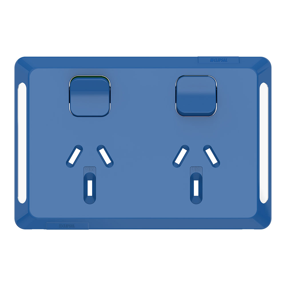
AV utilises "Patched Power" to consolidate satelite power to networked Power Distribution Units.
A patched power design consists of a Source end and a Destination.
The Destination is located at the satelite devices. It consists of a blue skinned Clipsal Pro socket and is cabled with TPS to the Source location. The outlet is to be lablled with both the PDU it is connected to, as well as the socket number (ie B314-115-PDU1/2 for PDU 1, Socket 2 in B314 Room 115)

The Source conolidation point contains one (or more) PDU's - available in 4 or 8 port versions - and a junction box, within which the TPS terminated. These TPS are then to transition to flexible appliance cable terminated in an IEC C14 plug with a sufficiently long trailing lead. One for each outlet.
- The junction box is to be secured to a wall or board in either the ceiling or on the wall.
- Wire nuts are not to be used
- The junction box should be labelled with the PDU number (ie B314-115-PDU1)
- Individual destination runs shall be labelled near the C14 socket with self-laminating labels or clear heat shrink.
In the event that Clipsal Pro outlets are not available Clipsal 413 or similar can be used and painted blue.